Also curious about the working principle of the Alia Density Meter? In this small article Alia Instruments provides more insight!
The Alia Density Meter is positioned in-line in the slurry pipeline. The density, defined as the slurry mass per volume unit, is measured under dynamic conditions, i.e. when the slurry is flowing. Inside the density meter, an actuator exerts a force with a known value and frequency onto the slurry, while an accelerometer measures its resulting acceleration. Newton’s second law of motion F = m x a, which relates the force F to the acceleration a via the mass m, is utilized to determine the mass of the slurry. The slurry volume is a known factor in the measuring tube of the meter. This means that the measured slurry density is nearly immediate and accurate, regardless of pipe diameter or slurry composition.
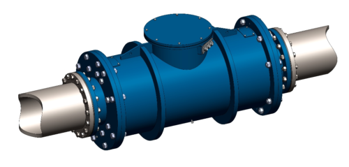
The central part of the density meter is the measuring tube through which the slurry flows. This tube consists of an outer part made of metal, giving stiffness to the tube, an intermediate part of polyurethane, and an inner part made of (natural or EPDM) rubber, giving flexibility to the tube. This rubber part gets in contact with the flowing slurry.
At the outer ends, near the position where the density meter is connected to the slurry pipe, the metal outer part of the measuring tube consists of bellows, allowing the middle part of the measuring tube to move in one radial direction. Rotational movement of the middle part is constrained by flexure leaf springs, and movement in other radial directions is prevented by the construction of the measurement device.
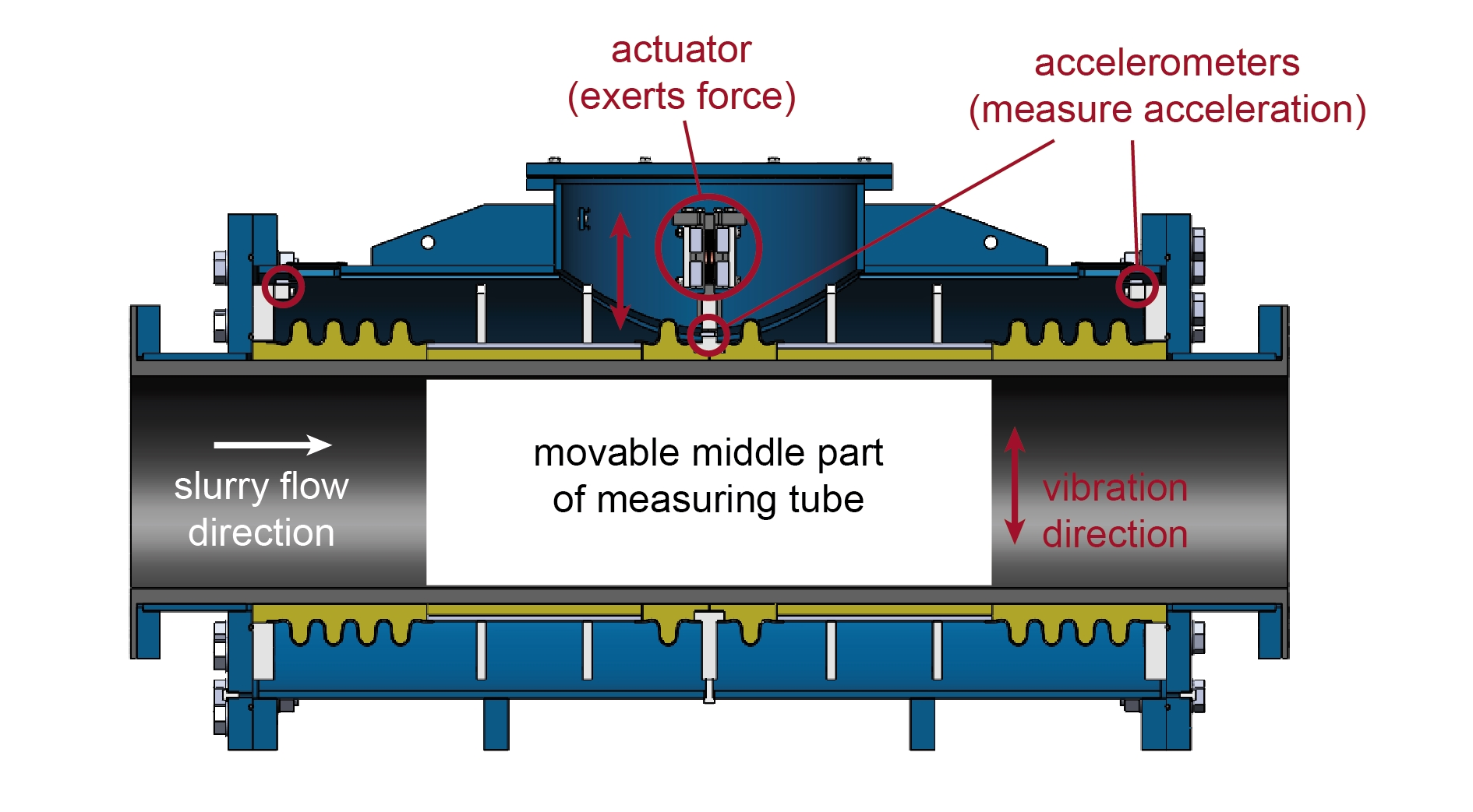
The actuator, consisting of a copper electrical coil surrounded by a permanent magnet package, exerts a force onto the measuring tube, allowing the middle part of the measuring tube to vibrate in the direction perpendicular to the slurry flow. The central accelerometer, which is positioned at the radial outer part in the middle of the measuring tube, measures the resulting acceleration of the measuring tube with the slurry flowing through.
In addition to the central accelerometer, two accelerometers are positioned near the outer ends (‘left’ and ‘right’) of the measuring tube. Besides measuring the position, velocity and acceleration at positions just adjacent to the movable middle part of the measuring tube, they also compensate for external influences to the measurement.
The mechanical model shows the suspended measuring tube including slurry flowing through, with mass m1 and (center of mass) position x1. L(eft) and R(ight) suspension consists of two springs with stiffness kL or kR, and dampening dL or dR.
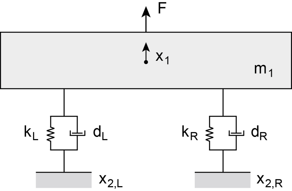
Based on the exerted force F and the measured acceleration x”1, the mass m1 of themovable part of the measuring tube including the slurry can be calculated.
When corrected for the mass of the measuring tube itself, the mass of the relevant slurry inside this tube is known. Dividing this mass by the inner volume of the movable part of the measuring tube reveals the density of the flowing slurry inside the measuring tube.
If you require more explanation, or have additional questions, please do not hesitate to contact us!